TRABANT 601
electronic Hall signal ignition board
"black box" (ignition box) is not required for its operation
Installation:
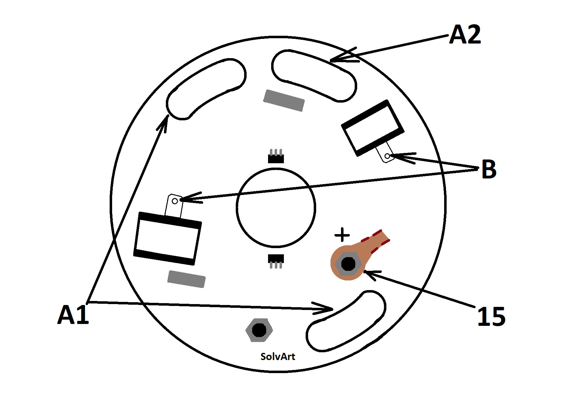
The breaker board must be removed. The ignition board must be installed with the connector pins facing outward. The positioning of the ignition adjustment groove (arrow „A1” – see on picutre) and the locator groove (arrow „A2”– see on picutre) clearly determine the position of the board.
Attach the cable lugs to the sliding contacts (arrow „B”– see on picutre).
Lead ignition current (from any ignition coil point) through the given 0.5-1.0 mm2 wire next to the outgoing cable to the board's threaded Ø 4 mm spindle (arrow „15” – see on picture). Use insulating tape or a cable tie to secure the wire to the cable.
Push the plastic ring onto the eccentric axis so that the slit faces outward / upward (arrow „C” - see on picture). The slit must fall onto the thicker side in the axis' symmetrical plane. The ring is shaped to fit the eccentric axis, so there is no other way to put it on.
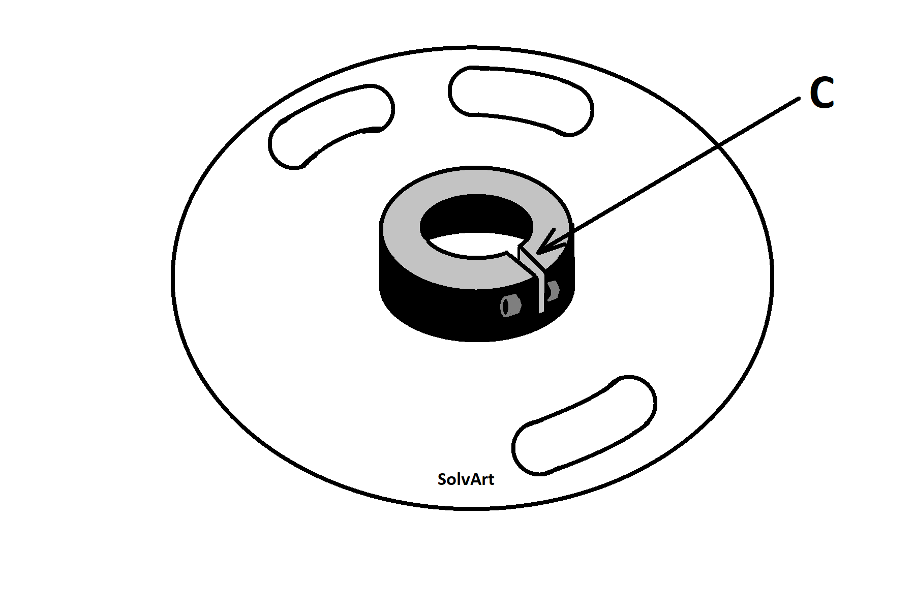
Press the ring onto the axis until it does not touch the board and there is a gap of approximately 1.0-1.5 mm between them (you can use the provided rubber piece as a measuring tool). The eccentric axis has a play of approximately 0.5-0.8 mm in the longitudinal direction, which is expected, but it cannot be greater than this. (Otherwise, an appropriate washer - flat piece of metal ring - is needed under the hex head screw.) Then tighten the ring onto the axis with the provided Allen key. Only tighten the screw enough to secure the ring. Do not overtighten as the plastic can crack! If the plastic ring needs to be removed for any reason, it can be easily pulled off by slightly stretching the slit (e.g. with a screwdriver)
The ignition time can be set to one of the cylinders (0° top dead point) with a strobe light or a test lamp and an indicator clock. The other cylinder is equally adjusted due to the precise geometry of the board, so this does not need to be adjusted separately.
If you manually rotate the crankshaft (test lamp setting), keep in mind that the electronics only work after a full revolution. Always turn the crankshaft in the forward direction, never in reverse, as it will give false values.
Since the board is grounded through the fixing screws, always turn off the ignition before changing the ignition time to protect the electronics. It is also possible to move the ring a little in both directions on the eccentric shaft, this also affects the ignition time!
Protect the board from mechanical damage while adjusting. Put a drop of paint on the finally tightened screws and nuts to avoid future loosening. Place the cover of the ignition housing back precisely.
The ignition coil remains in its original position. (Only normal coils, which are otherwise used for the breaker system, can be used for electronics. The use of high-performance "transistor" coils is prohibited, and any malfunction resulting from their use is not covered by warranty.)
Make sure that the ignition is not turned on when the engine is not running as this can cause overheating and potential malfunction of the electronics and ignition coils.
Only use a spark plug cap with a resistor. (R = 5-10 kΩ)