Cart is empty.
Click here to buy
Installation manual for MZ ES / TS 12V electronic ignition board
The ignition motherboard contains the power output stage, so there is no separate output stage module ("black box")
The ignition works on the principle of optoreflux, so the alternator magnetic field of the dynamo does not interfere with stable operation. Before starting the installation, be sure to inspect the ignition network of the motorcycle. This can be done practically with an ohmmeter in addition to the removed battery. The most critical points: the area around the battery terminal, grounding cable ends, fuses. Old, hardened wires should be replaced with new ones by crimping reliable cable ends. You may also want to consider replacing the old fuse holder. (It may be advisable to install a much more reliable battery terminal type).
Installation:
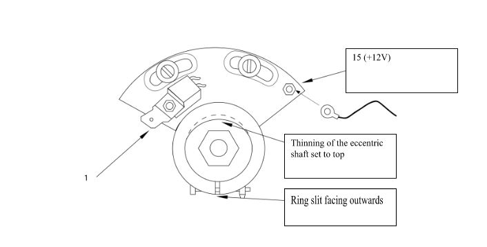
- The circuit breaker board must be removed with a capacitor. Screw on the electronic system board with the screws in the center of the grooves. (approach the factory pre-ignition)
- Next to the incoming cable, route the ignition current through the black wire included in the package, practically from point 15 of the ignition transformer. Attach the other end of the cable to the M2.5 threaded nozzle on the motherboard, or fix it with a drop of paint to prevent it from loosening.
- The crankshaft is then positioned so that the white part of the plastic ring included in the package is above the transmitter. The internal design of the plastic ring follows the shape of the eccentric shaft. Therefore, this can only be pulled onto the shaft in one way.
- Ignition ON, push the ring inward on the shaft until the red indicator light on the system board is at its maximum brightness. This is done with an air gap of about 1.2-1.5 mm encoder ring (this operation is performed in a slightly darkened room, because very strong light can interfere with the setting!)
- The air gap MUST NOT BE below 1.2 mm !! (Risk of rubbing.)
- The pre-ignition must be adjusted by rotating the crankshaft in the direction of rotation (e.g. by means of a test lamp indicator clock or a caliper method). The pre-ignition value depends on the engine type: 2-3.5 mm. (Since the electronics are grounded on the bolts, always switch off the ignition first when changing the pre-ignition. It is also possible to move the ring a little in both directions on the eccentric shaft, this also affects the pre-ignition!)
- After the final pre-ignition setting, tighten the ring on the shaft with an Allen key. Apply a drop of (fixing) paint to the properly tightened screws. Do not overtighten as the ring may crack!
- Only a transformer used for an otherwise interrupting system is suitable for an ignition transformer. The use of a high-power, high-current ignition transformer is prohibited, as it can damage the electronics.
- It is also recommended to inspect the high voltage side of the ignition system. Also check the resistance of the ignition pipe by measuring ohms. This is appropriate if the value is between 4-10 kΩ (kiloohm). The resistor provides interference suppression, the absence of which can cause ignition disturbances and ultimately failure of the ignition module. Make sure that the ignition is not left on when the engine is stopped, as the ignition transformer and electronics may overheat or malfunction.
In order for the system to work reliably, be sure to check that the motorcycle is properly charged (13.8-14.5V is acceptable at 12V).
Warranty: 24 months from the date of purchase, which is only valid for installation in a specialist workshop.